ReLEAF Perfusion Bioreactor
Overview
A closed loop for continuous production and physical containment.
The ReLEAF perfusion bioreactor is a closed culture system designed to grow engineered Bacillus subtilis continuously while physically retaining the cells. Culture circulates through the lumen side of a hollow‑fiber membrane, and smaller soluble products can cross into a collection stream.
Purpose
2.1 Shift from Direct Release
The original design placed the engineered bacteria, a transgenic plant growth‑promoting rhizobacterium, directly into the soil. Once released, their spread, expression and dose are harder to control, which risks unintended GMO release.
Only the protectant they produce is needed, so we moved the cells into a contained bioreactor, from which only the product is designed to leave.
2.2 Choice of a Hollow‑Fiber Bioreactor
B. subtilis natively secretes proteins into the surrounding medium, so the product can be separated from the cells.
The hollow‑fiber membrane makes that separation the containment barrier as well: its pores are designed to pass smaller soluble products to the shell side while retaining whole cells on the lumen side.
Batch or perfusion: four weeks of culture
ModelWith medium exchanged continuously and the cells held back by the membrane, the culture is designed to hold a high density for weeks.
How this is computed
Each culture is three relative quantities: cell density X, nutrient S and protectant P.
μ(S) = μmax S / (KS + S) dX/dt = μ(S) X (1 − X/K) − kd X − (1 − R) D X dS/dt = D (Sin − S) − μ(S) X (1 − X/K) / Y − m X dP/dt = q X − D PGrowth is logistic, capped at K. D is the perfusion rate and R = 1 means the membrane retains every cell; the batch runs at D = 0, is harvested every N days, and takes half a day to turn around.
Illustrative values: μmax = 24, kd = 0.4 and m = 0.1 per day; KS = 0.05, K = 1, Y = 0.8, Sin = 1, X(0) = 0.02; fourth‑order Runge–Kutta steps of 0.0025 day.
2.3 Compact, On‑Site Operation
A compact bioreactor can sit near the farm, so protectants are produced locally and applied closer to when they are needed, with less reliance on centralized production and transport.
Hardware Highlights
3.1 Hollow‑Fiber Containment
The 0.2 µm hollow‑fiber membrane separates the culture from the product stream by size (6.1).
3.2 Perfusion Culture
The culture circulates continuously. Circulation is designed to admit fresh medium and remove product while the culture stays in the closed loop.
3.3 Integrated Monitoring
In‑line OD600 from our self‑built photometer is logged with flow rate and pressure, so a run is followed with no sample drawn.
3.4 Layout of the Loop
The system has two fluid paths, which meet only at the membrane wall.
Culture loop
Medium reservoir → peristaltic pump → in‑line photometer → fiber lumens → reservoir. The path holds the organism and is closed for the run; the only access is the dual Luer valve.
- Reservoir1 L medium; 300 mL working volume in a 500 mL vessel, first three runs
- Inoculum20 mL multi‑overnight B. subtilis culture
- Flow rate94 mL/min
- Stirring200 rpm magnetic
Protectant harvest
The space around the fibers. It fills by diffusion across the fiber wall, is drawn off through the shell ports, and carries protectant to delivery.
- MembranemPES (modified polyethersulfone) hollow fiber
- Pore rating0.2 µm
- ModuleCobetter Biophsep MiniLab
- Area200 cm², eleven fibers
- Deliverysoil or hydroponic line
The system, stage by stage
As designed Two circuits, one membrane wall
- 1
Culture in the reservoir
A stirred 1 L medium reservoir, with a pH probe in its cap. Expression is induced by green light from the AIoT stress predictor.
- 2
Reading without opening the loop
The peristaltic pump draws culture past the Luer sampling valve, through the in‑line photometer and into the top of the membrane column. The pump acts only on the outside of the tubing, so the fluid path stays closed.
- 3
The only crossing
The fiber wall is the only place the two circuits touch; the organism is retained on the lumen side.
- 4
Return to the reservoir
Culture returns down the lumens and through a pinch valve to the reservoir. A small pump is designed to dose potassium hydroxide (KOH) from a second bottle into this return line.
- 6
Sensing of the product stream
An optical sensor reads the product stream after the membrane.
- 7
Exit to delivery
Shell‑side fluid leaves the machine for a soil or hydroponic line.
- 8
One closed loop, one open path
What crosses the wall to the field is the protectant with anything else below the pore rating: medium components, vesicles and debris. Containment is physical at the membrane, and the Luer sampling valves are where procedure still matters.
3.5 Software
The bioreactor is run from one controller interface, the Digital Twin, which logs every sensor reading on the loop and commands the valves. Its models have so far run on recorded data after each run, and a person approves every decision.
| Function | What it covers |
|---|---|
| Live readings | OD600 from the in‑line photometer, pH, flow rate, and pressure at all four membrane ports |
| Live control | The pinch valve and four Luer valves, from the controller interface |
| Sensor alarm | An autoencoder trained on the first 120 h of the 434 h run; it flagged the failing photometer 26.7 h before its reading failed |
| Batch forecast | A Kalman filter, 2 to 12 h ahead. A growth rate registered on 1 October came out inside its interval on the 14 to 16 October run |
| Reading gate | On the OD channel since 14 October: a window that fails its own checks holds the last accepted value and is flagged. It turned away 31 of 1,083 windows on that run |
| Not yet integrated | Green light and dissolved oxygen, each tested separately |
The training and testing of each model, and the field sensors the next version adds, are described on the Digital Twin page.
Engineering Cycles
Three tracks, as in the team’s cycle diagram: pressure and flow across the hollow‑fiber membrane (4.1), pump and valve control (4.2), and the whole loop run together in the integrative bioreactor (4.3). The bacteria‑growth and photometer cycles and the long‑term run are on the photometer page.
4.1 Hollow‑Fiber Membrane
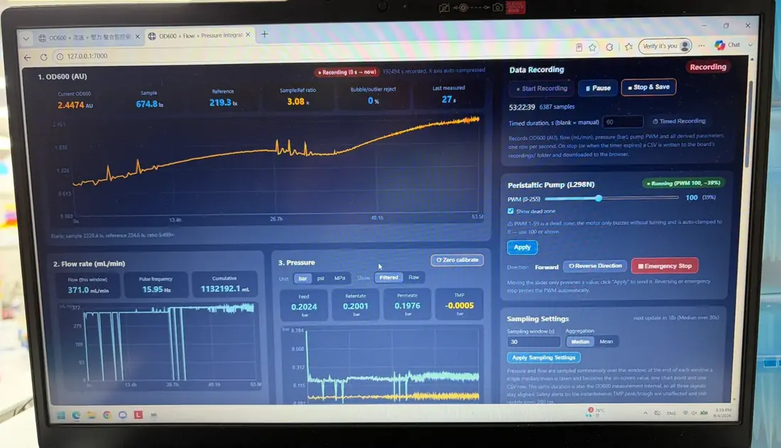
This track measures transmembrane pressure (TMP). Three of its four transducers (feed, retentate and permeate) logged near 0.20 bar each on the 4 September dashboard, which also shows about 371 mL/min. The 14 to 16 October run turned that measurement into a trend: the pressure the module needs beyond what clean water needs at the same flow rose from 2.0 to 3.8 kPa across 42 h, with two excursions where the permeate line was opened. Nothing had to be cleaned, and no replacement interval follows from one run (7.1).
The pinch valve intended to regulate pressure is in prototype 2; its design is not on record.
4.2 Pumps & Valve Control
The pinch valve’s servo and the KOH dosing pump are recorded under prototype 2; the pumps are listed in 5.1.
4.3 Integrative Bioreactor
Where the tracks meet: pump control, the pinch valve and pH, and the in‑line photometer in the loop.
Prototype 1 of 3
Prototype 1 – Pump Control
First integrated run: constitutive ACC deaminase production
Design
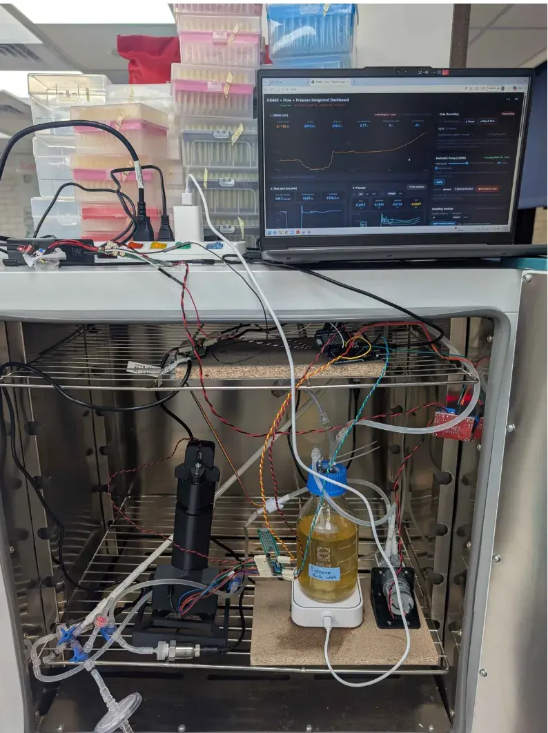
This prototype tested integration of the whole loop. ACC deaminase is under a constitutive promoter, so the strain expressed continuously and light control was outside the test; the rest of the loop ran as laid out in 3.4.
Build
Test
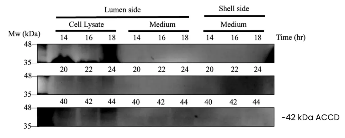
Engineered B. subtilis was cultured in the loop, and a Western blot of shell‑side medium gave a faint band consistent with ACC deaminase (~42 kDa).
Learn
ACC deaminase reaches the shell side, but expression is weak.
Prototype 2 of 3
Prototype 2 – Pinch Valve & pH
Fixed for the build: the pinch valve is driven by an STS3215 12 V servo motor, one near the Out‑Lumen end of the membrane and one near the In‑Lumen end, each about 2 inches from the connection. The pH probe sits in the reservoir cap and plugs into the Arduino, and the CKP‑DC‑S08 pump (5 mL/min) draws from a small KOH bottle through a Luer valve into the Out‑Lumen line.
Prototype 3 of 3
Prototype 3 – In‑line Photometer
Optical density read from inside the culture loop
The in‑line photometer monitors optical density in the loop: culture passes through a flow cuvette with a 2 mm path, where OD600 is read without drawing a sample. Its own cycles are on the photometer page.
Design
We wanted a full growth curve from one uninterrupted run. Every manual OD600 reading removes culture and risks contamination; in‑line measurement is designed to remove that risk.
Build
The photometer runs on an Arduino UNO Q serving a web dashboard on the local network, so a long run can be followed without opening the system (photometer page, 3.5).
Final Design
5.1 Specifications
Ten specifications define the lab design, as recorded here and in the assembly notes.
The ten specifications, as recorded10 rows
| Specification | As recorded |
|---|---|
| Working volume | 300 mL of LB in a 500 mL reservoir in the first three runs; 1 L from September. Two reservoirs: the 1 L medium reservoir and a small KOH bottle. |
| Membrane | mPES hollow fiber (Cobetter Biophsep MiniLab), 0.2 µm pore, 200 cm² over eleven fibers |
| Flow rate | 94 mL/min on the culture loop; about 371 mL/min on the 4 September dashboard (4.3) |
| Stirring | Magnetic stirrer and stir bar, 200 rpm, in the reservoir |
| Tubing | Biocompatible BPT tubing, called for after a prototype leaked at the pump; still planned |
| Temperature | 37 °C for the growth curve on the loop; 22 °C for the 400 h photometer run |
| Pumps | ZP4000‑N79H electric peristaltic culture pump, 1 L/min; liquid pump, 1.5 L/min; KOH pump, 5 mL/min |
| Sensors | In‑line photometer for OD600; four pressure transducers, one at each membrane port (In‑Lumen, Out‑Lumen, In‑Shell, Out‑Shell), each behind its own filter; flow meter; pH sensor in the medium reservoir’s cap; droplet sensor (6.2); a turbidity meter for protectant level, in the doc's user‑manual outline |
| LEDs | 3 m green‑light LED strip, switched by the stress prediction to induce expression; green at about 535 nm switches expression on and red at about 670 nm off (CcaS–CcaR). |
| Pressure regulation | Pinch valve (4.3), driven by an STS3215 12 V servo motor and fitted near the Out‑Lumen and In‑Lumen ends of the membrane |
Containment & Safety
In agricultural fields, engineered organisms must not enter the wild. The bioreactor is designed to keep engineered B. subtilis inside while protectants leave through the membrane.
6.1 Physical Containment by Size
The membrane's 0.2 µm pore is smaller than the reported diameter of B. subtilis cells (0.25–1.0 µm), so whole cells are intended to stay on the lumen side while smaller soluble products cross to the shell side.
What gets through the membrane wall
ModelCells and pores at one scale.
To test whether whole cells crossed, medium was collected from the lumen and shell sides after 24 h at 37 °C.
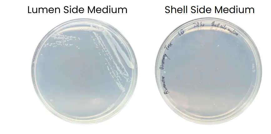
On LB agar the lumen‑side sample grew colonies and the shell‑side sample grew none, so culturable B. subtilis remained on the lumen side under the conditions tested. The second plating on record, 2 mL of shell‑side medium (6 June 2026), also grew none (photometer page, 2.1).
6.2 Leak Prevention
A closed bioreactor can still leak. Two monitoring mechanisms are fitted: one for liquid escaping the system, one for faults within the membrane.
External Leaks: Droplet Sensor
A droplet sensor beneath the setup detects liquid escaping from the tubing or connections; the software is designed to raise an alert.
Internal Faults: Transmembrane Pressure
The system is designed to monitor TMP, where a sudden or abnormal change can indicate a leak, breach or blockage before it is visible.
Four pressure ports, two alarms
ModelThe four transducers, and which of them registers a fault.
TMP = (Pin,L + Pout,L)/2 − (Pin,S + Pout,S)/2
= (0.20 + 0.20)/2 − (0.20 + 0.20)/2 = 0.000 bar
This card runs a small model of the module’s four pressure ports in the browser.
Neither system has been tested with a deliberately induced leak or breach (7.1).
Limitations & Future Plans
7.1 Current Limitations
-
Protectant Transfer Rate
No shell‑side concentration or transfer rate has been measured; the blot shows only that it crosses.
-
Long‑Term Membrane Integrity
The two platings test the barrier at one time point. One fouling trend is now on record, 42 h on 14 to 16 October, and no induced leak or breach test is (6.2).
7.2 Future Plan
We plan a sealed cartridge‑style replacement system for the culture and medium, so that a contained module can be replaced during servicing without opening the bioreactor. Planned testing covers longer operation, membrane fouling, cartridge lifetime, protectant transfer rate and field‑relevant conditions.
Reproduction
8.1 Materials List & Cost
Cost by component
From the cost sheetEach line of the sheet below, largest first.
| Component | Qty | Cost (TWD) |
|---|---|---|
| Hollow-fiber membrane | 1 | 7,800 |
| Pump | 4 | 2,500 |
| Pressure sensor (one per membrane port) | 4 | 1,800 |
| pH sensor | 1 | 2,450 |
| Flow meter | 1 | 350 |
| Sampler | 1 | 400 |
| Air filter (medium reservoir) | 1 | 300 |
| Filter (pressure‑sensor lines) | 4 | |
| Reservoir (1 L medium, small KOH bottle) | 2 | 180 |
| Magnetic stir bar | 1 | 120 |
| Luer valve | 5 | 150 |
| Luer lock | 20 | 400 |
| Spectrophotometer (reference, not built in) | 1 | 14,000 |
| Parts total | 16,450 | |
| Sheet total, with the reference spectrophotometer | 30,450 |
The sheet's total adds the column, about US$960 at its own conversion. The spectrophotometer is a reference instrument and not part of the build, so without it the parts come to NT$16,450. The build has four pressure sensors and five filters (confirmed 15 Oct) while the sheet was costed for three and one, so these totals leave out the fourth sensor and the four pressure‑line filters.
8.3 Culture Medium
Organism
B. subtilis 168 in every run to September: wild type in the 400 h run, and secreting ACC deaminase constitutively in prototype 1 (4.3). B. subtilis WB800 secreting ACC deaminase constitutively in both October runs
Inoculum
20 mL multi‑overnight liquid culture
Medium
LB; volumes and temperatures in 5.1