Hydroponics Floating Plate
Purpose
2.1 Standardized Hydroponics for Laboratories
Laboratories that grow Arabidopsis in liquid medium improvise with cut foam, taped mesh or fixed plates, which differ between laboratories and runs. The floating plate prints from four STLs on a standard fused deposition modelling (FDM) printer, so another laboratory can print identical geometry. The design is intended to give the same root depth, spacing and conditions regardless of operator.
2.2 Limitations of Fixed Plates
The first prototype was a fixed plate over a liquid chamber. The level had to stay within a narrow window below the platform: below it, the roots lost contact; above it, the platform flooded. The level fell through plant uptake and evaporation, so it was topped up by hand, and each top-up let conditions diverge between replicates.
Design Requirements
R1 · Constant root depth
Hold root depth constant for the whole run without manual top-up. Sections 2.2 and 4.
R2 · Thirteen seedlings
Carry 13 Arabidopsis seedlings. Section 5.
R3 · Integral flotation
Float on its own buoyancy, with no separate float attached. Section 4.
R4 · Standard printer
Print in PLA on a standard FDM printer. Section 7.2.
R5 · Assembly without adhesives
Assemble without adhesives or fasteners. Section 5.
Buoyancy Design
The plate floats on sealed air in a chamber inside each pontoon (). Sizing the chambers is a displacement problem: at the freeboard that places the roots in the medium and the crowns above it, the plate must displace its own mass, the seedlings and any water the print takes up. We repeated the calculation after every design change, because wall thickness and footprint change mass and displacement together.
- MassPlate, seedlings and any water the print takes up.
- BuoyancyMedium displaced by the pontoons below the waterline (hatched).
- FreeboardThe height at which the two balance.
The displacement at each waterline defines the plate’s load line (). In water at 1.00 g/cm³, each cubic centimetre displaced supports one gram. Along the straight pontoon sides, displacement rises 3.51 cm³ per millimetre of draft, so every 3.5 g lowers the plate about 1 mm. No printed plate has been weighed, so the load line has not been checked on a real part.
- Waterline drawn in : 54.2 g floats at 9.2 mm of freeboard.
- Slab underside at the water: 79.4 g and 3.2 mm. Beyond it the whole slab displaces, so each gram lowers the plate less.
- Slab top awash: 111.9 g.
- Solid PLA: the sixteen parts would weigh at most 92.6 g and float at 1.9 mm of freeboard.
Displacement at each waterline7 waterlines
| Freeboard | Draft | Plate alone | Assembled |
|---|---|---|---|
| 18.2 mm | 6.9 mm | 22.4 cm³ | 22.4 cm³ |
| 15.2 mm | 9.9 mm | 32.9 cm³ | 32.9 cm³ |
| 12.2 mm | 12.9 mm | 43.4 cm³ | 43.4 cm³ |
| 9.2 mm, as drawn | 15.9 mm | 54.0 cm³ | 54.2 cm³ |
| 6.2 mm | 18.9 mm | 64.5 cm³ | 65.5 cm³ |
| 3.2 mm, slab underside at the water | 21.9 mm | 75.9 cm³ | 79.4 cm³ |
| 0, slab top at the water | 25.1 mm | 105.9 cm³ | 111.9 cm³ |
Freeboard is the height of the slab top above the water; draft, the depth of the pontoon bottoms below it. Displacement is the volume of the printed shell below the waterline, including the sealed air, computed from the STLs. Assembled values add the submerged parts of the handles and seed holders. The calculation assumes no air is trapped under the slab.
Geometry and Mechanical Design
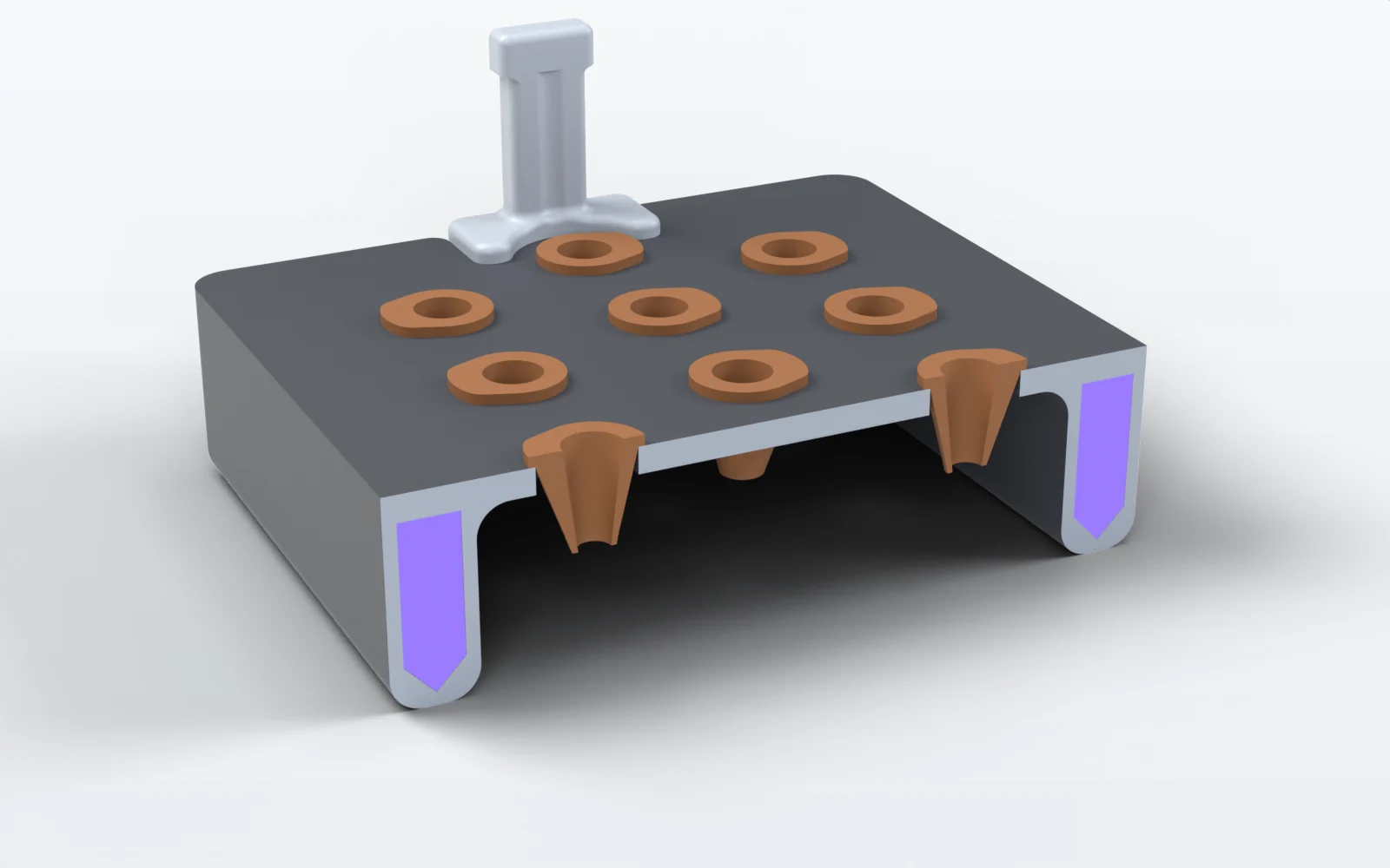
- 1Teardrop pontoons, printed without support.
- 2Integral flotation: slab, pontoons and chambers print as one part.
- 3Clip-in handles, to lift the plate without touching the seedlings.
- 4Corner poles for washer ballast, first floating plate only (section 6).
- Sealed air chamber, hidden below the slab
- Pontoon, hidden below the slab
- Clip-in handle
- Sealed air, in section
- Printed plate, in section
- Seed holder
Measured geometry10 dimensions
Engineering Cycles
The plate’s three prototypes, each as a design–build–test–learn cycle.
Prototype 1 of 3
Prototype 1: Fixed plate
Design
A plate fixed at a set height over a liquid chamber.
Learn
It worked only while the level was corrected by hand (2.2).
Prototype 2 of 3
Prototype 2: First floating plate
Started 6/25
Design
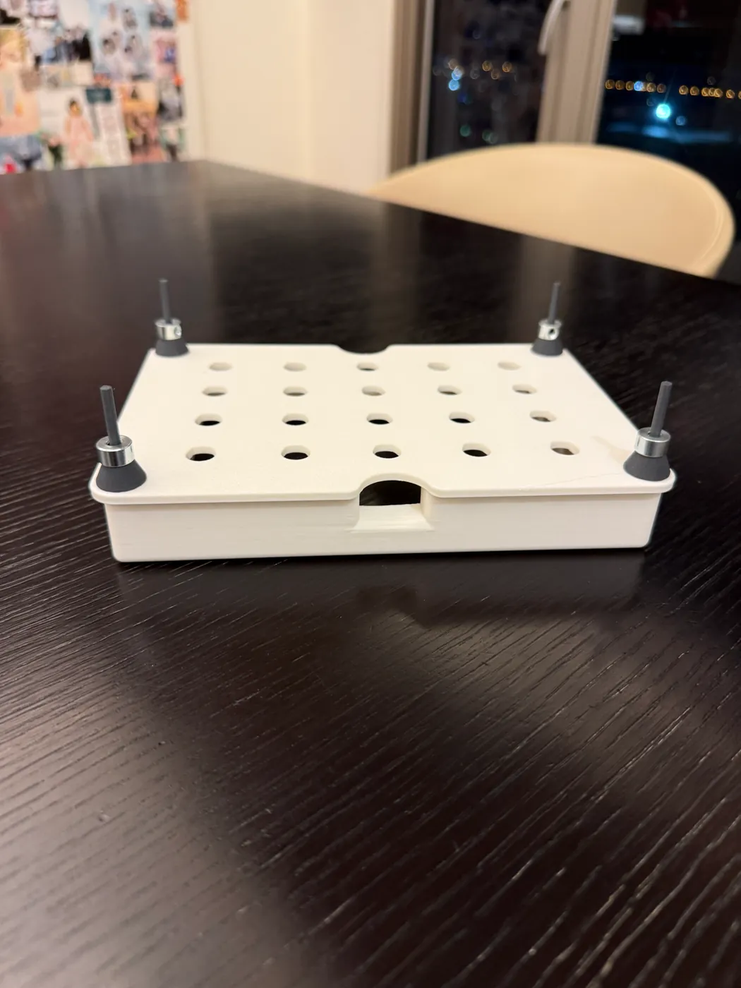
We moved the flotation into the frame. Corner poles carried washers that trimmed the freeboard without reprinting.
Build
Learn
The poles provided the buoyancy margin and were removed once the chamber volume was tuned (section 4).
Prototype 3 of 3
Prototype 3: Current design
Design
Smaller footprint, clip-in handles, no ballast poles; this design is reproduced in section 7.
Side views are schematic and not to scale; the CAD of the current design is in .
Reproduction
7.1 Bill of Materials

Printed parts4 parts, 16 pieces
| Part | Qty | Volume, each | Cost |
|---|---|---|---|
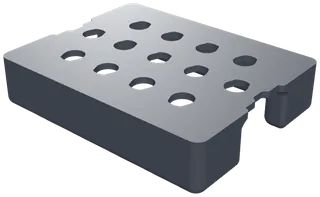 Floating plate | 1 | 63.60 cm³ | |
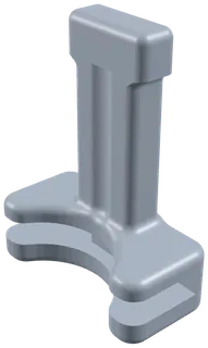 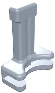 Handle, left and right | 2 | 2.76 cm³ | |
 Seed holder | 13 | 0.43 cm³ | |
| Total | 16 | 74.72 cm³ in all |
All four parts print in PLA. Volumes are solid CAD volumes; filament use depends on wall count and infill. No cost is recorded.
7.2 Print Settings
Print settings4 rows
- Material
- PLA
- Printer
- A standard FDM printer
- Infill
- 15% gyroid in the pontoon sections
- Supports
- None
Layer height, wall count and print orientation are not recorded.
Design Files
The four STLsone per printed part, millimetres, Z up
- 1Floating plate
Print one.
- 2Left handle
Clips onto one end of the slab.
- 3Right handle
Mirror of the left handle.
- 4Seed holder
Print thirteen.